


The following detailed information comes from a brochure issued by the
Bristol Siddeley Engines Ltd in August 1958
POWER FOR BOMBER COMMAND
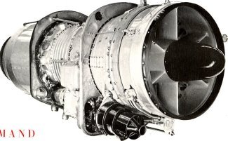
The Bristol Olympus is a high-thrust turbojet engine having a light weight and a low specific fuel consumption.
![]()
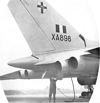
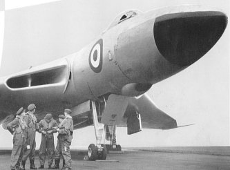
Olympus engines of the Mk 200 series have been selected to power the Avro Vulcan B Mark 2 bomber, which will form the spearhead of Bomber Command of the Royal Air Force.
The latest version of which details may be released, the Olympus 201 (B 01, 7), completed an official Type Test at a rating of 17,000 lb in June 1958, and is believed to have the highest thrust: weight ratio of any type-tested turbojet engine in this class.
The earlier Olympus Mk 200 (B 016) was type-tested at a thrust of 16,000 lb in January 1957, and it was the first engine in the world to be officially approved and go into production at so high a rating. Flying hours are already beginning to accumulate.
Greater thrusts have frequently been recorded on the test-bench, and further development of the engine, both with and without reheat, is in progress.
The unique combination of light weight for high power and low specific fuel consumption is largely due to the two-spool layout of the Olympus, and is precisely suited to the requirements of the modern bomber, which must have the maximum possible height over the target, with high speed and immense range carrying its designed war load. Moreover, particularly in versions employing reheat, the Olympus is remarkably well suited to operation at transonic and moderate supersonic speeds. Its basic lightness combined with reheat operation provides an exceptional thrust: weight ratio for the high-altitude interceptor, and the all-weather fighter, while its low fuel consumption for cruising gives long duration, both at high and low altitudes.
Earlier versions of the Olympus power the Vulcan B Mark 1 already established in service with Bomber Command. These versions include the Olympus 101 of 11,0001b thrust, the Mark 102 of 12,0001b thrust, and the Mark 104 which has a Type Tested rating of 13,0001b static thrust.
The performance of these engines, and in particular their case of handling, has received high praise both from pilots and ground crews. The rapidity of acceleration and the General excellence of control are direct results of the two-spool principle employed, which was pioneered by Bristol and has now been adopted by other famous manufacturers.
Compression takes place in two stages, by two compressors arranged in series, each driven by its own separate turbine. Each compressor automatically takes up its optimum speed, independently of the other, under all conditions, with the result that high power and great efficiency are maintained to high altitudes, and the engine is endowed with greater flexibility of operation and case of control. Starting is also made easier, because only the high‑pressure spool has to be accelerated to the speed at which the engine becomes self‑driving, and acceleration from idling to maximum speed under three seconds is made possible.
![]()
The Olympus 100 Series engines, which have now been in service in Avro Vulcan aircraft of Bomber Command for over two years, have an excellent reputation for their handling qualities.
Pilots have made "slam" accelerations and decelerations at the highest altitudes at which the aircraft have been flown, well above 50,000 feet. The engine response on these occasions was excellent, as it is at all altitudes, the highest altitude representing the most severe test of the engine handling characteristics.
The Olympus 100 Series engines are fully cleared for operation in severe icing conditions, and thus represent the highest standard of anti‑icing protection.
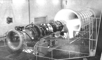
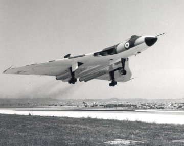
The cruising thrust of the Olympus engines is sustained to a remarkable degree at high altitudes. This was demonstrated in the English Electric Canberra flying test bed in which the 100 Series engines were flight tested, and which, powered by these engines, achieved the World's Height Record of 65,890 feet, and is now evidenced by the excellent altitude performance of Bomber Command Vulcans.
Mean Mean Mean Date of 1st production
Thrust SFC Bare engine
lb/hr/lb Weight
Olympus 101 11,0341b 0.817 3 6151b July 1954
Olympus 102 12,0091b 0.811 3:7931b April 1956
The table shows the average performance and weight of production engines of the Olympus 100 Series. The total number of engines over which this average was taken runs well into three figures.
The engine has now reached the stage of development at which it rarely requires anything more than routine attention between installation and removal for overhaul at the end of its "time-expired" life. Routine maintenance is very simple and consists of little more than removing the oil and fuel filters for cleaning, and inspecting the engine for oil and fuel leaks and for signs of accidental damage.
The Vulcan has carried out numerous overseas tours, including visits to Australia and New Zealand, East Africa and Rhodesia, South America. Canada and USA as well as many of shorter duration. In one case three minor engine defects were reported, but on all the other tours there have, at the time of writing, been no engine failures or defects whatsoever.
Although, since the first deliveries to the RAF in the summer of 1956, the Vulcan has been in service with an Operational Conversion Unit where it works under more arduous conditions than are normal in a squadron, the number of involuntary engine removals has been remarkably small. Altogether tens of thousands of flying hours have been completed by engines of the OCU and the squadrons equipped with Vulcans, and an average figure of 1,800 hours per unscheduled removal has been achieved for all Olympus engines in RAF service. This includes removals due to all causes, not only those ascribed to engine defects.
During the whole of this period, there have been only three cases of an engine failure in flight, and one of these was due to the entry of a large foreign body.
To sum up, one may quote the Under Secretary of State for Air, Mr C I Orr-Ewing, who said that the Olympus-powered Vulcan had "probably had the minimum amount of teething trouble of any aircraft introduced in the RAF over the last 10 years.
![]()
The advantages of two-spool systems of compression become more apparent as the pressure ratio is increased. This figure is continually being raised in the quest for still higher performance.
This higher performance can be obtained in three ways: by higher efficiencies of the individual components Such as the compressor and turbine; by raising the maximum cycle temperature at the entry to the turbine; and by raising the compression ratio from the inlet to the delivery of the compressor.
Component efficiencies are already relatively high, so that further improvements become progressively smaller and more difficult to achieve. The effect of variations of the maximum temperature and pressure ratio are interlinked, but it is always true to say that increasing the maximum cycle temperature results in higher thrust per unit of mass flow, and therefore per unit of frontal area, but is limited by the life of the available materials at the increased temperature. However, an increase in the maximum cycle temperature results in higher jet velocities and therefore in lower propulsive efficiencies with a corresponding increase in specific fuel consumption. Nonetheless, the use of higher compression ratios enables higher maximum temperatures to be employed with advantage; it also results in a direct improvement in specific fuel consumption.
A higher pressure ratio could easily be achieved if weight and bulk were no object by using a very large number of stages, the work done by each being proportionately reduced. However, weight and bulk are at premium. In the design of aero‑engines and, in order to achieve low weight and to reduce the length of the engine, the work done by each stage must be as high as possible without sacrificing the handling and acceleration characteristics. When the rotational speed of the compressor departs from the design speed', so the ratio of the density the inlet to the density at the outlet of the compressor changes.
For example, at low engine speeds the pressure ratio from inlet to outlet is less than the design value, and the density ratio is correspondingly affected. Among ways of ensuring efficient operation of the compressor at these low density ratios are included variable swirl varies, which alter the angle of the stator blades as between low and high speeds, and bleed valves at an intermediate stage of the compressor which enable the velocity through the inlet end of the compressor to be increased without affecting the outlet end. Both these expedients, however, involve a complex operating mechanism. In the Olympus, the problem is overcome by dividing the compressor into two spools, which can run at the optimum speed to accommodate the different density ratios.
This results in good handling characteristics, since the tendency to surge even during rapid acceleration is eliminated, and ensures that both sections of the compressor are running under efficient conditions irrespective of the engine speed or the operating altitude. This enables the excellent power and fuel consumption characteristics of the Olympus to be maintained at high altitude.
With the two-spool layout, starting is also greatly simplified because it is only necessary to rotate the high pressure system, thus reducing the size of starter motor required.
Air Intake Casing
The Olympus 102 has a seven-stage low-pressure compressor and an eight stage high-pressure compressor, delivering air to a 'cannular' combustion chamber containing ten flame tubes, which feed single‑stage high‑pressure and low‑pressure turbines.
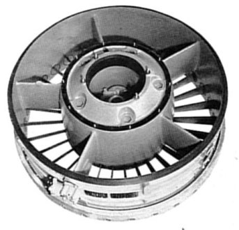
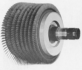
Low Pressure Compressor Rotor
The intake casing is a magnesium-zirconum casting with radial struts supporting the central front main bearing housing, which also carries the generator within the nose fairing. The intake casing houses a ring of entry guide blades, which are of fixed incidence. With the Olympus two-spool compressor arrangement, variable entry guide vanes are rendered unnecessary.
The low‑pressure compressor rotor consists of seven rotor discs, one of which is of steel, the remainder being of light alloy. They are sandwiched between the compressor drive shaft and the front rotor centre, or stubshaft, the discs being located by tubular dowels threaded over the eight through‑bolts which clamp the whole assembly together.
Fir‑tree root fixings are used to secure the compressor blades to the respective discs.
The low‑pressure compressor casing is made in two sections, split on a diameter, and is a light‑alloy casting.
Grooves of dovetail section house the seven rows of aluminium alloy stator blades, and the single row of exit blades. The stator blades are located by stop bolts against which they are clamped in groups by wedge bolt assemblies.
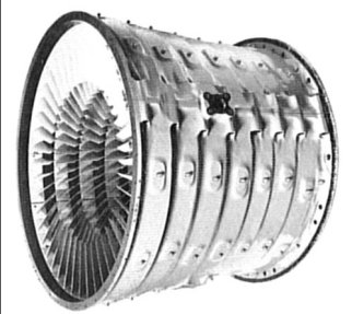
Low Pressure Compressor Casing
The intermediate casing, situated between the two compressors, is a magnesium zirconium casting which carries the rear bearing of the low-pressure compressor and the front bearing of the high‑pressure compressor rotor. Mounting faces for auxiliaries are provided on this casing in two groups, one for those driven from the low-pressure compressor and the other for those driven from the high-pressure rotor. The latter include the fuel pump and the pressure and scavenge oil pumps. A centrifugal breather within the casing is also driven from this rotor, and the starter motor, which drives the high-pressure compressor, is also mounted on the casing.
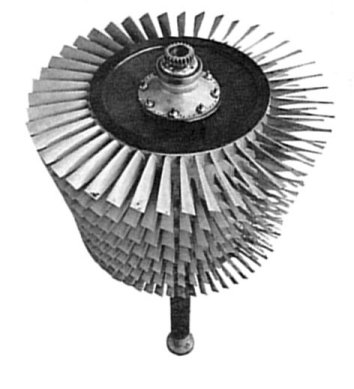
The construction of the high‑pressure compressor is similar to that of the low-pressure unit, but owing to the higher temperature of the airflow, steel is widely used rather than light alloy; for example, the two-piece stator casing is of steel, as are the rotor discs and all blades. The rotor discs are located radially relative to each other by Hirth couplings on each disc boss, and axially by means of a nut on the driving shaft holding the pack of discs ill compression against an integral flange oil the shaft. The rotor blades, entry guide vanes, stator blades and two rows of outlet guide vanes are all of steel and are cantilever mounted in the same way as in the low‑pressure Unit.
High-Pressure Compressor Rotor
The sheet steel delivery easing consists of inner and outer walls joined by ten radial struts, the inner wall supporting the rear bearing of the high‑pressure compressor. The outer wall carries the main engine mounting trunnions.
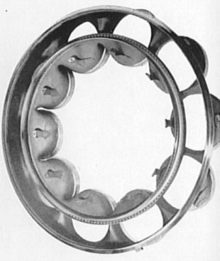
The combustion system of the Olympus 102 is of the 'cannular' type, which an earlier version of the Olympus was the first British turbojet engine to use. The combustion chamber consists of inner and outer casings forming an annular space which contains ten flame tubes.
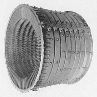
High-Pressure Compressor Casing
The front end of the outer easing is secured to the rear flange of the delivery easing, and the rear end to the first-stage turbine easing. The outer casing comprises front, centre and rear units, the centre unit being cylindrical and split on the horizontal centreline, so that access to the flame tubes may be achieved by removing either the top or bottom half. The front section carries the front ends of the flame tubes and the duplex burners, while the rear section encloses the high-pressure turbine stator blades and the high-pressure rotor.
Turbine Entry Duct
Each flame tube is in two parts, the flame tube head, which divides the primary air from the remainder, and the main cylindrical body of the flame tube. The latter is located at its front end by part of the flame tube head, and at its rear end fits in the turbine entry duct. Axial location is by means of a locating bolt. Interconnectors partway along each flame tube link it with its neighbours facilitating lighting‑up.
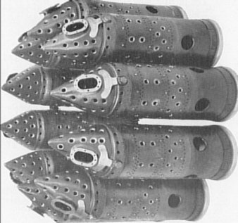
A Group of Flame Tubes
The turbine entry duct unit receives the outlet ends of all ten flame tubes and is supported from the outer casing.
The high‑pressure turbine shaft is mounted in two bearings and drives the corresponding compressor shaft through a toothed coupling. The low-pressure turbine shaft also has two bearings, one of which is on the down-stream side of the disc, and drives the low-pressure compressor through a coupling coaxially within that of the high‑pressure rotor.
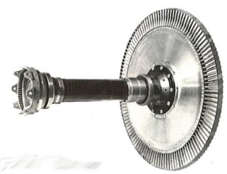
High-Pressure Turbine Rotor
Both high‑pressure and low‑pressure stator blades are precision cast in segments of four and they are mounted at their outer ends from the turbine casings. The low-pressure stator blades are dogged at their inner ends to an interstage seal.
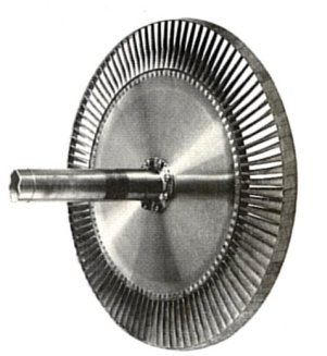
Low-Pressure Turbine Rotor
Both sets of rotor blades have shrouded tips, the Olympus having been the first British turbojet to adopt what has since become standard practice. The blades are attached to the turbine discs by fir-tree roots engaging serrations in the disc peripheries.
Surrounding the turbine rotors are a pair of turbine casings which are bolted together, and these in turn are surrounded by a thin heat‑shield.
The exhaust annulus is bolted to the rear of the low-pressure turbine casing, and bolted in turn to the downstream end of the exhaust annulus is an articulated exhaust cone section, to permit small malalignment between the jet pipe and the engine. The jet pipe is attached to this section by a quick‑release manacle clamp.
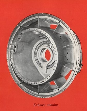
Exhaust Annulus
The fuel system includes a high-pressure pump of the swashplate type feeding the duplex burners via an air/fuel ratio control, a full-range flow control and a flow distributor. Governors are provided to limit the maximum rotational speed and also to control the cruising rotational speed.
![]()

Hope you found it interesting - regards JB !
![]()
Compiled by John Beal in support of the project to get XH558 flying again - please pledge your support now ! I hope you have found this web site interesting and entertaining. Complaints, comments and suggestions will all be actioned, click here.